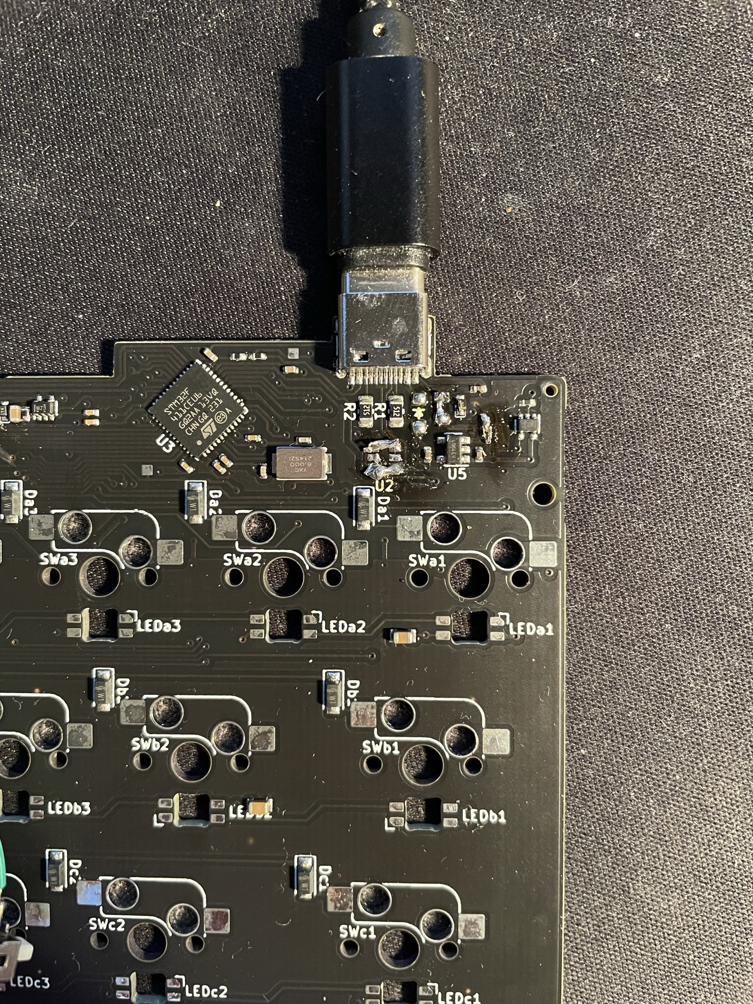
I got my first prototype PCB of the new Lakemountain Keyboard left half from JLC PCB!
Already before testing it I knew there would be some small issues with it because of me ordering before actually checking my schematic properly… The main one being the USB D+/D- signals not being connected to the MCU, just the SRV05-4 ESD protection diode array. ESD surge protection is a good thing that I did not design into my last keyboard, but it would be even better if the USB signals actually reach the MCU, derp!
However some quick PCB surgery and I can still use these prototypes. I just removed the SRV05-4 from the PCB with my hot air station and bridged a few pads and voila!
Before powering up the first time measured some continuity on with the multimeter and made sure there where no other obvious mistakes, like a GND/VCC short. Everything to avoid the magic smoke. After connecting the voltages I measured looked fine. Stable 5V in on USB and 3.3V from the regulator, great!
Next thing to try was of course to try to flash the stm32. I had prebuilt a .bin with qmk that I threw together for this keyboard. Still needs a lot of configuration but should be good enough for it to run and get recognized as a keyboard on my computer.
I quickly realized that I could not get the stm32 to boot into the bootloader.
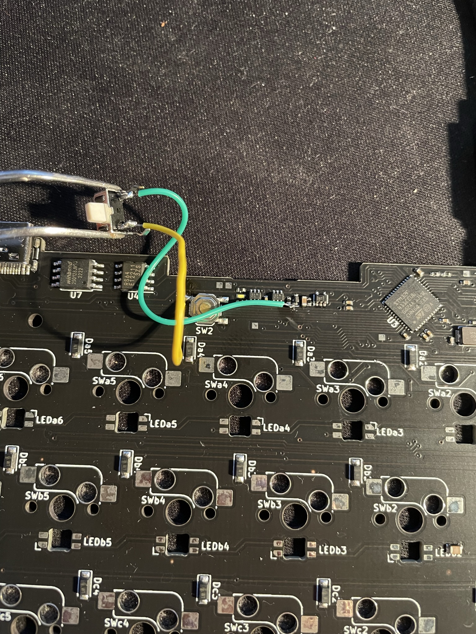
The stm32 require you to to bridge BOOT0 to VCC (via BOOT0 button or jumper), short RESET to GND (via RESET button or jumper), and then let go of the BOOT0 bridge. This I had solved on my board with a smarter reset circuit inspired by the BonsaiC4. This allows me to just press one reset button to enter the bootloader instead. However somewhere in my redesign of the PCB schematic I made a mistake and kept the reset switch from my old design, directly shorting the NRST pin to VCC instead of triggering the actual reset circuit, derp again!
Back to the soldering iron and this time I just added an external switch connecting the proper trace to VCC when pressed. And to my slight surprise the PCB booted into the bootloader immediately when pressing the button. A quick firmware flash using QMK Toolbox and the PCB was recognized as a keyboard!
All of the problems I described in this post has actually already been fixed in the schematic and PCB layout. I for other reasons already redid the reset circuit which made me accidentally fix the reset issue, and I had already noticed the USB problem before. Next up, configure the QMK firmware with all the features I want to try and make sure they work as expected. I’m still waiting for the SK6812 LEDs and the hotswap sockets also so when they arrive I can try those features.
That’s it for today.