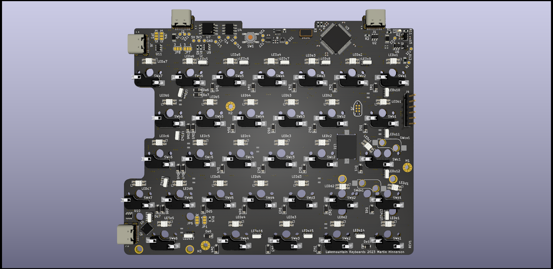
Here is and interactive BOM for the new updated version. It’s pretty stacked with stuff now which required some pretty disgusting routing in some places but it should be fine now.
One thing you can see is that I in some places had to slightly misplace the switch LEDs to allow for ISO/ANSI layout choice. The LED will not be directly under the switch LED hole there but the light should still come through fine. This is just one of the design choices I had to make to accompany for the modular design.
I also now support the weird offset versions of the Caps Lock key that you often find if you take keycaps from for example a Logitech keyboard. There the keycap stab holder is not centered directly in the middle but offset slightly.
With the hotswap sockets now rotated the pins on one side will stick out a mm or so outside of the PCB. According to my 3D model this should however not be a problem when it comes to mounting it in the case since there is some margin. If it becomes a problem anyway I can make the wall a bit thinner or in worst case snip of the hotswap pins with some pliers.